Cycle Fatigue: We’re Not Talking About the Tour de France…
by Omar James, MSME, Technical Consultant
June 7, 2022
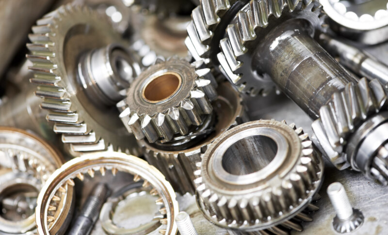
In common industrial machinery, gear-trains are utilized for energy transfer, power output, or for conversion to some form of electrical output. Under extreme operating conditions, rotational components such as spur gears, bearings, and shafts may be susceptible to failure. Some modes of failure could be influenced by external forces, such as operator error, maintenance, overloading, or vibration. Recognizing these modes of failures can visibly represent the history of any given mechanical system.
For mechanical systems, engineers carefully estimate the lifespan of the equipment while it is used in the field. For mechanical components, there are four failure mechanisms: corrosion, erosion, fatigue, and overload. Transmissions, timing systems, pump drives, and servos, to name a few, all have one critical component, which are the gear teeth. Gears are normally mated to a shaft, which is driven or drives a source. Each mating component is subject to a degree of wear given the conditions of the system that is operating. For a rotating system, an operator may be most concerned about fluid lubrication as components are susceptible to higher wear rates outside of the lubricant’s temperature operating range. An operator may also be concerned about vibrations in the system as this motion could cause harmonics in the system. With both the influence of vibration and lack of lubrication over time, fatigue can be easily introduced into a system, which we describe as cyclic fatigue.
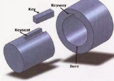
Shaft keys are machine elements that prevent relative rotation between two rotating parts. These are frequently seen in transmissions, where these keys are placed directly between a spur gear and an input shaft. Each key is placed in a square-shaped keyway, which behaves as a joint between a hub and a shaft (Photograph 1, below).
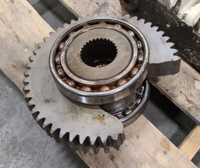
Now that we have established a background on failure modes and the machine elements they impact, let’s visit a recent field investigation. How could such a robust gear cause such a catastrophic failure in a pump drive system (Photograph 2, below)?

Photograph 1

Photograph 2
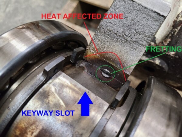
Taking a few steps back, we can use the process of elimination in our root cause analysis. In short, fatigue and overload are evident in this scenario. Taking a closer look, the finer details and condition of the elements can explain the history of this entire machine in great detail. Photograph 3 (below) illustrates a gear and shaft, which is joined together by a key. Ultimately, heat was the leading cause of the presented failure. By summation of the elements, vibrations were induced, which caused fretting. The excessive fretting generated heat, which led to crack initiation. With the continuation of rotating cycles of the system, stresses rose, cracks propagated, and we are presented with fatigue failure. Other indications of the fatigue failure were exhibited in the material, often referred to as beach marks. These markings indicate the successive positions of the advancing cracks over a given cycle period.

Photograph 3
We have a staff of experienced consultants who are keen to these fine details. In this case, Loss Solutions Group was able to recognize this mode of failure and provide our client with a cause of loss.
Please contact Omar James, MSME, Technical Consultant, with questions or to discuss claims involving gear-trains or other mechanical equipment at 866.899.8756 ext. 744 or ojames@losssolutionsgroup.com.

